A heating system to last 100-plus years…
Recently we were asked to design an electric underfloor heating system for a rather special client involved in the private space industry. The system had to last 100 years, have multiple built-in redundancies, and we think you may find some elements of our solution rather interesting.
 Heat Mat was recently approached by the designer of a high-end residential property who was creating a generational residence that their client imagines will be in use for 100-plus years. They wanted to work with Heat Mat to design a system to their client’s exacting requirements, the main one being that the systems should be expected to work for 100 or more years with minimal intervention. Yes, Heat Mat offers a Lifetime Warranty, but that wasn’t enough for them. Their client was not concerned about the up-front cost of the underfloor heating, they simply wanted a heating system with the greatest possible lifespan, and we were tasked with specifying and manufacturing it.
To make the job even more challenging, their client is heavily involved in the private space industry and was keen to follow some of the same principles they use there for life-critical systems with multiple built-in redundancies. They wanted us to include at least three redundant heating systems:
- A hot redundancy – A system that works alongside the primary heating elements, and automatically takes over the additional heating load if the primary heater fails.
- A warm redundancy – With the underfloor heating powered down, but ready to automatically take over in the event the primary and hot redundant systems were to fail.
- A cold redundancy – A system that sat there, completely unconnected to the other systems, and that would require human intervention to get it up and running if it was required.
Accepting the challenge, we got to work.

We really had a blank design brief other than that the finished floor types were to be marble and granite. To start, we brainstormed the main things we could do to lower the risk of any heating system failing over the next 100 plus years.

Electric underfloor heating cables are already very well set up for a long-life expectancy. They are powered by electricity, the main power source of the future, and do not have the manifolds and pipes of a wet underfloor heating system, which can become blocked or otherwise fail. If the heating cables are mechanically damaged (for instance, someone drilled through a cable), they are easily repaired, and the cables and mats themselves have no electronic parts that can fail. The initial batch of suggestions we produced apply to nearly any electric underfloor heating system, even when installed in a more normal domestic setting:
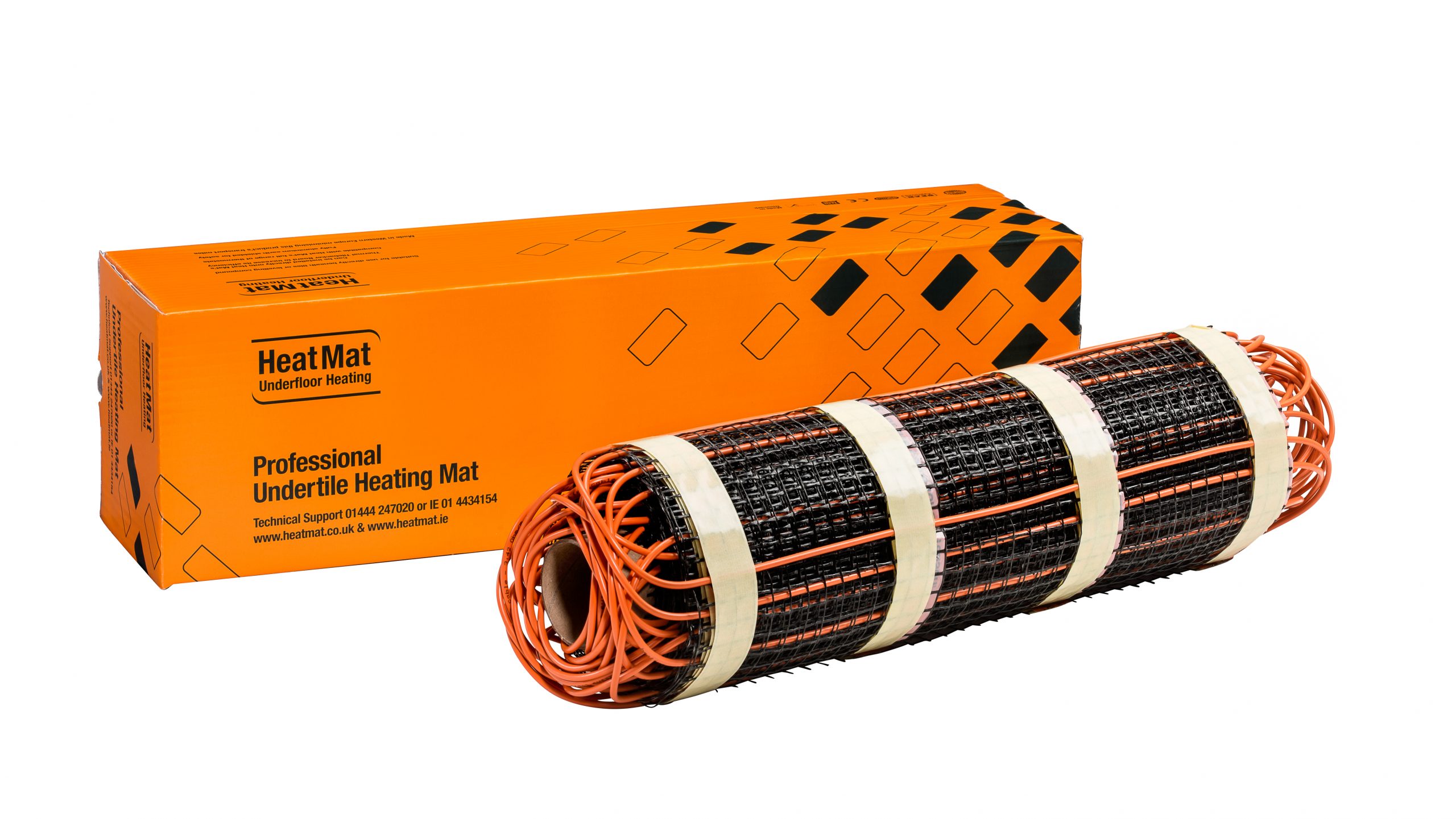
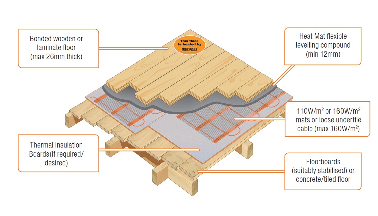
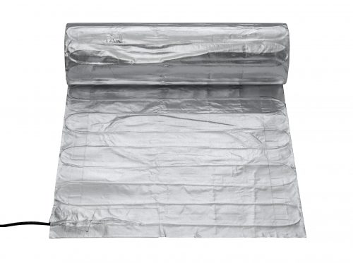
- System choice – Use a low-profile heating cable that is under-rated, not running at its full design output per linear metre. In our case, that could be using our PKM mats running at 160W/sqm. On this mat the cable is running at 16W/metre, but it is designed to run at up to 25W/metre, therefore it is under very low stress as it warms up and cools down.
- Ensure it is mains-Voltage – The higher the voltage, the less stress there is on a cable, so we specified our 230/110V cable rather than a low-voltage 12V or 24V system. Low-voltage systems also have no earth, which means the system may not so easily cut out if required to protect itself. Low-voltage systems also require transformers, which will usually have no more than a 5-year warranty, and a limited lifespan.
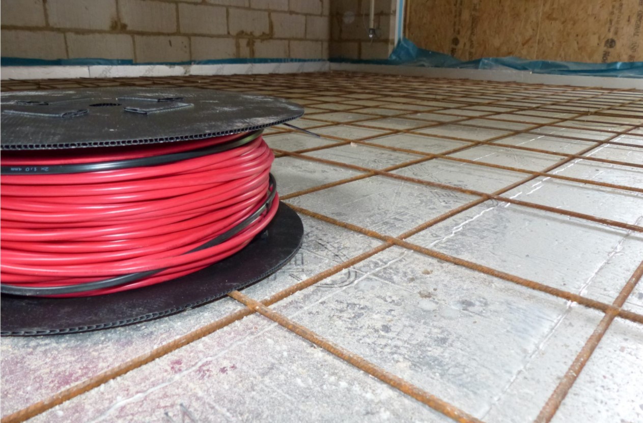
- Cover the heating mat in a suitable 12mm levelling compound – This ensures that there is a very stable surface around the cable designed to help it pass on its heat efficiently.
- Fit multiple floor sensors and use industry-standard options - Floor sensors have a failure rate of approximately 1:1,000 over a ten-year period. If I was installing a system for a prospective 100 plus years, I would fit three floor sensors for each system, so that if one failed you could simple switch to the next one with minimum fuss; the chance of all three failing over 100 years is a very low 1:1,000,000. Our floor sensors have an industry standard 12kOhms rating, so they will still be compatible with new control systems many decades from now.
- Fit the coldtail connection and end termination with particular care – These sections of the heating system are handmade and designed to fail if they overheat. They could be installed in such a way to ensure that these sections could be more easily accessible if required for repair if something had caused the system to overheat.
- Make sure the system is correctly fitted! – Nearly all failures come about due to incorrect installation, so ensuring that the system is fitted correctly, and all electrical checks are carried out will offer great protection. Use an installer who knows what they are doing and has read the relevant instructions and electrical regulations. Take advantage of Heat Mat’s Tech Team’s free of charge support to approve the installation either in person or via video call/photos.
- Controller longevity – The contactor in an electric underfloor heating controller has a limited life expectancy based on the number of operations (on/off cycles), with Heat Mat’s OJ-manufactured units rated to have among the highest number of operating cycles in the industry. Although there are already many controllers still running after 20 years, the electronics in them can fail, and the contactor can give out. Many people replace their controllers every 10 or 15 years to keep up with the latest technology. For this system, we specified spare controllers to be fitted in the future if required, or alternatively, replacement controllers could be purchased in the future and installed when one failed. An alternative would be to run the entire system through a Building Management System using the temperature sensors and an external contactor. In the end, though, both of these items would likely need replacing before 100 years were out anyway, so all of these solutions are acceptable.

The above recommendations are the most straightforward and, as already mentioned, can apply to nearly any system. However, this client wanted us to highlight any additional measures they could take to preserve the longevity of the heating systems. We put our heads together to come up with a few more, some of which we had already put into practice on Heat Mat’s major infrastructure projects and in Arctic and Antarctic designs:
- Create custom low-Wattage heating cables – By underpowering a heating cable well below its maximum design output you reduce the stresses on the cable. Heat Mat can manufacture heating mats using our cable rated to 25W per metre but running it at only 5W per metre, meaning the cable is under exceptionally low stress from thermal expansion and contraction.
- Install multiple heating mats/cables – Rather than using one large heating mat to heat a room, you can use multiple small mats, so that if one were to fail it would be unnoticeable to the client (as long as the mats were beneath a 55mm plus screed to spread the heat).
- Protection from lightning strikes - If a property is hit by lightning, this can cause the system to fail, so ensuring that there is ample lightning/surge protection is wise.
- Protection with an arc-detection device – Although 30mA RCD protection is always required, additional protection with an arc-detection device will ensure that the system is protected from the very rare issues caused by arcing in the connections.
- Limit the on/off cycle – If you really want to ensure the system's maximum longevity, you could prevent the system from turning on/off regularly, by allowing it to overshoot the target temperature by 2°C, and then fall back to the target temperature. This will limit the physical stress on the cable from the heating up and cooling down cycles and can be combined with a low output cable.

After providing details on all the above measures, we finally came to building in the redundant systems. There were several options we could have followed, but the choice we took was:
- Primary system – Multiple small heating cables per room, custom made to run at an ultra-low output per linear metre, all placed beneath a 12mm levelling compound. If one cable were to fail, it would be unnoticeable in the floor temperature above the system. This system had three floor sensors placed at different points around the room, as did all other systems.
- The hot redundancy – Beneath the primary system, an identical secondary system was specified beneath another 12mm layer of levelling compound; this system had the same target temperatures as the primary system and worked in tandem with it. Either system had the power to fully warm the room if operated by itself.
- A warm redundancy – We repeated the setup a third time beneath the hot redundancy, but with 160W/sqm heating mats beneath a further 12mm of levelling compound. The reason for using a different product setup was just in case there was some form of imperfection in the main cable plastics or metals that was not discovered for many decades; in this case, the 160W/sqm mat cable should not have the same weakness, as it was a different design and extruded separately. This system was controlled to initially target floor and room temperatures below the main two systems, so in theory it would never come on if either of the other two systems were working correctly.
- A cold redundancy – The final system was a deep screed heating cable laid beneath the above three systems, and beneath a 20mm layer of levelling compound. As with the heating mat, it was a different type of cable to guard against material failure in one system also effecting other systems, and the system was in place but not connected to the property’s electrical circuit meaning that even in the case of a lightning strike, the system could not be damaged.
The final design meant that there were four heating systems in each room, all capable of independently heating the areas. Two of the redundant systems would automatically take over the heating in the case of a failure of other systems, while the third needed to be manually switched on. Based on the above we are confident that the property can be heated by a Heat Mat system well into the 2100’s.
Credit for space photo
Photo by Aldebaran S on Unsplash